Learn about imaging mode
A typical modern transmission electron microscope has about
half a dozen electron lenses or more, and at least three
sets of ‘shift and/or tilt’ coils to get the most important
lenses aligned properly. Electron microscopes are indeed
quite complicated. Manufacturers think that their potential
customers will be frightened if they are made aware of all
the complicated things that go on inside the microscope.
Most modern microscopes are therefore controlled by a
computer that tries to make everything look as simple as
possible.
Now it is possible to do a lot of reasonable microscopy
without understanding anything about how the microscope
actually works. However, it is my opinion that it is very
easy to explain what’s going on, and once you know what’s
going on, it’s much easier to remember how to do microscopy
without resorting to lists of commands or badly-written
manufacturers manuals. Your results will also be much
better and much more reliable.
To proceed, we are going to have to do a bit more theory.
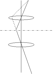
Theory: When we have two electron lenses mounted on the
optic axis, we can form an image of the source as before,
and then form an image of that first image. To understand
this, lets just think about one point in our object plane:
it could be one point on the filament we thought about in
the optical experiment. It gives out electron in all directions, like
this:

The beams, which are flying out in different directions,
then go into a first lens, which can focus them all to a
point, like this:
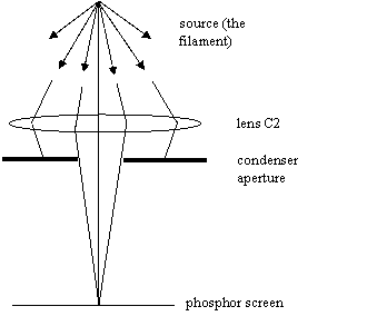
In part 1 imagined we had a phosphor screen
immediately below the condenser lens. In fact this was not
quite true: the phosphor screen was nowhere near the cross-
over of the lens we were adjusting, C2. In truth, there was
nothing at all at the cross-over of C2 except free space,
like this:
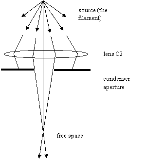
But the effect of having a cross-over in free space is the
same as having another source at that point in space: the
cross-over just sprays electrons in a range of directions
downwards from a single point in free space. That means we
can have another lens, below the first lens, which focusses
the new source of electrons onto the phosphor screen, like
this:
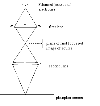
Once we have two lenses, each of which can be changed in
strength (by turning knobs on the electron microscope), then
all sorts of new and exciting things become possible. Call
the top lens the ‘first’ lens, and the bottom lens the
‘second’ lens. (In part 1, we used C2, which is the
second lens of the condenser system, as we’ll see below.)
There is whole set of different excitations (strengths) of
our two lenses that will still give us an in-focus image of
the source on the phosphor screen. Look at the next three
diagrams:
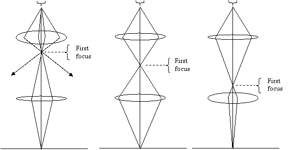
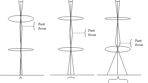
In the first diagram the lens is strongly
excited (you can tell it is strong because it is bending the
beams that go near the edge of the lens through a large
angle and the lens is thick) and the second lens is weakly excited. In the next
diagram, both lenses are excited by the same amount. In the
last diagram, the first lens is weak, and the second lens
is strong.
It is a key thing to remember that whenever you are playing
with two electron lenses which are focusing an object, if
you turn up one lens (i.e. make it stronger, or ‘over-
focus’, or turn its knob clockwise) then you must turn the
other lens down (i.e. make it weaker, or ‘under-focus’ it,
or turn its knob anti-clockwise) to keep the image in focus.
Do you remember that in the optical experiment the ray-diagrams
we drew had all the beams going through the of centre of the
lens? It told us that when we move focus distances, the
magnification changes, but the rays through the middle of
lens didn’t tell us about the focal distance itself. Well,
in the above diagrams, all we were thinking were the focal
distances of the two lenses. We drew beams that came from
one point in the object and went through different parts of
the lens. Lets now redraw the diagrams with a different set
of rays: those that come from different parts of the object
but that all go through the middle of the lenses, like this:
We have to say two important things about these diagrams.
The first (and most important thing) is that we can see that
as we change of excitations of the two lenses, the
magnification of the image changes. Obviously, this is the
most important function of an electron microscope.
The rays that go through the middle of lens can be thought
of like a lever. The lever pivots at the middle of the
lens. If the pivot point of the lever is near top end of
it, then wiggling the top of the lever (which is when the
beams explore different parts of the object), makes large
movements at the other end of the lever: the image of the
object is magnified. In the figures above, we have two
levers, one above the other. By making combinations of
lenses, we can achieve any magnification we like, and still
keep the image in focus.
The second (unimportant and rather pedantic) thing to notice is that we seem to have broken a
rule in these diagrams. We have bent the rays in free space, at the planes where they reach focus
according to the previous diagram, no matter where they
arrived within the plane. Surely beams can’t just bend,
without having a lens or deflection coil? True. In fact,
what we are doing is changing our attention from one set of
beams that pass through the first lens, to a second set of
beams that pass through the second lens. It is useful to do
this, because if we know where the lenses are focussed, we
can easily work out how the magnification is affected.
If you are worried about the bending beams in the figure above,
think of it like this. For every beam that we draw that
goes through the second lens, there was a beam that went
through the first lens (but not through its middle point)
and arrived at exactly the right place and at the correct
angle to set off directly toward the centre of the second
lens. Lets draw such a beam as a dotted lines in a new
version of the picture, like this:
Remember: When we draw a ray diagram, we can only work out
where a lens focusses by considering beams that don’t go
through the centre of the lens. When a lens gets stronger,
these ‘off-axis’ beams are bent more strongly, and so the
focus gets closer to the lens. To work out how the
magnification is affected, think of beams that go through
the centres of all the lenses as levers. You can start a
new lever whenever you get to the plane of focus of the
previous lens.
Now lets do some experiments to show how all this works:
Ask the demonstrator: Please load a nice and easy test specimen
into the microscope. An ideal specimen is something like a
thin holey carbon film, scattered with micron-sized
polystyrene spheres, which has been shadow coated with a
gold film. A combined test specimen of graphitised carbon
and gold islands is also good. Align the condenser system,
find the eucentric height, and focus the objective lens.
Set a low spot size. Get me a nice image at moderate
magnification.
Show me the magnification knob, the objective focus knob,
and the specimen shift controls.
Gosh! Four more variables at your command (if we count
specimen shift x and y as two variables). Play around with
your nine variables. Can you remember what they are?
- Brightness or ‘intensity’: control of the strength of a lens called C2
- Electrical shift x: For shifting the illumination around the place
- Electrical shift y: Also for shifting the illumination around the place
- Mechanical shift of the condenser aperture, x: For physically shifting the condenser aperture.
- Mechanical shift of the aperture, y: as above.
- Specimen shift x: For moving the specimen around the place
- Specimen shift y: As above
- Focus: control of the strength of a lens called the ‘objective’
- Magnification: something that controls at least a pair of lenses, which changes the magnification somehow.
Let us tell you how the electron microscope is built. When
we draw a rectangular thing like this:

we mean that there is a block of lenses - perhaps as many as
five lenses - that change things like magnification. For
the time being, we are only going to worry about two lenses
- C2 and a lens called the ‘objective’. C2 is inside
something called the ‘condenser system’, which we’ll learn
about in more detail later. The microscope is like this:
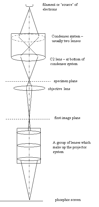
When you use the microscope in what is called ‘image mode’
(which is what we are doing at the moment), what you see on
the phosphor screen has gone through lots of lenses. But
the important thing to know is that these other lenses,
which are represented by the lower block above, just change
the magnification of what we see on the phosphor screen.
They always remain focussed on the image plane of the
objective lens. Lets call this ‘the first image plane’, as
shown on the diagram above.
If the demonstrator did you everything you suggested, then the
object plane of the objective lens is the specimen itself,
also marked on the diagram above.
C2 is actually above the specimen. It can focus an image of
the source directly onto the specimen. In image mode, it is
used to spread the beam all over the specimen. Focussing on
the source is
something you do to align the condenser system and its
aperture, and also to use the microscope in scanning mode
(if it is equipped with scan coils).
Now you can really understand what you were doing in the
first part of the guide. To begin with, we had no specimen in the
microscope, but all the lenses were set up as shown above.
The block of lower lenses (which, incidentally, is called
the ‘projector system’) was forming an image of the ‘first
image plane’ on the phosphor screen. The objective was
forming an image of the ‘specimen plane’ onto the ‘first
image plane’. The condenser C2 was forming an image of the
‘source’ onto the ‘specimen plane’.
In other words, it really was as if C2 was forming an image
onto the phosphor screen, because all the other lenses were
just acting to transfer whatever was happening in the
specimen plane down to the phosphor screen (give or take a
bit of magnification).
However, we now have some more controls...
The magnification knob does things inside the projector
system (see above)
in order to increase or decrease the magnification of what
we see on the phosphor screen. Unless you are using a truly
ancient microscope, you won’t have to worry about the
individual lenses in the projector system. When you change
the knob, a computer automatically works out different
settings of the lenses inside the projector system to change
magnification, while at the same time keeping the first
image plane in focus.
Experiment: Change magnification and see what happens. Go
up in magnification. As well as the image getting bigger,
the screen gets darker - why? Change the brightness knob
(remember - it should always be over-focussed). Find a hole
in the specimen. Get an image of the source. Turn C2 up
again (over-focussed). This is called ‘spreading the beam’.
Try changing the ‘focus knob’, which will change the
objective excitation (i.e. the strength of the objective
lens). What happens? Can you focus on the specimen?
Ask the demonstrator: To explain the ‘focus step size’ knob on
the objective lens, if it exists. Explain the fine focus
switch on C2 (brightness or intensity), if it exists.
Explain to me how to change the size of the condenser
aperture.
Re-practice aligning the condenser aperture. Put in a large
aperture. Focus C2 to form an image of the source again.
Change the focus of the objective lens by a large amount:
what happens to the image of the source? Can you explain
why?
Play around with the 12 variables you have now learnt about
and talk to the demonstrator. Do you understand everything? Do
you understand the ray diagrams. If not, ask the demonstrator to
explain in more detail.
Ask the demonstrator: Show me how to insert a selected area
aperture (the bottom-most aperture assembly). Show me how
to select different aperture sizes and move them about.
Experiment: Where do you think the selected area aperture
(often know as ‘SAD’ for ‘selected area diffraction’
aperture, for reasons which are explained later) is actually
positioned? It seems to be in the specimen plane. Is it?
What happens when you try to focus on it with the objective
lens? Does that tell you where it is? If you can’t work it
out, ask your demonstrator to explain.
Ask the demonstrator: Show me how to take an image onto
photographic film or the CCD camera (whatever is available).
Explain the exposure meter to me. Show me the button that
makes an exposure.
Arrange the image at a pleasing magnification at over an interesting area of specimen, check
the exposure and then press the exposure button.
There! Quite easy really, you’ve taken your first
experimental result on a transmission electron microscope.
Time for a cup of tea (or, some other refreshment)….
But before you go for a cup of tea,
Ask the demonstrator: Show me how to turn off the beam of
electrons.
Whenever you leave an electron microscope, you must leave it
in a ‘safe’ state, and it very important to learn how to put
it into a safe state so that in future, when you are first
left alone on the microscope, you will know how to seek help
if you get stuck.
The demonstrator will show you the filament control. After tea,
we can discuss how the source of electrons works. In the
meantime, do the following:
Put the electron microscope into a normal imaging state.
That is to say, make sure you can see a neat disc of
illumination on the specimen, the magnification is
reasonably low (say 3000-5000x), and there are no grid bars
(that support the specimen) in the way of the beam. If the
selected area aperture is in, take it out. These
precautions are worth taking so that when switch the beam on
again you can be confident that the microscope is in a
normal state and you will see the beam when it comes on.
When you can see a well-illuminated image, turn down the
filament current knob (turn it anti-clockwise) according to
the instructions of the demonstrator. What the demonstrator says will
depend on what sort of filament is in the microscope. If it
is a tungsten filament you can turn it right off. If it is
a LaB6 (called by microscopists a ‘Lab-six’) you should turn
it slowly, and only to about 50% of its usual operating
limit. If this is the case, the demonstrator will show you a
meter or a figure on a computer screen that monitors the
current heating the filament: turn down the knob until it
reaches the figure or setting that the demonstrator wants you to
leave it at.
While you turn down the filament, watch what happens on the
phosphor screen: after a few clicks, the screen gets darker
and darker as the electrons stop coming out of the source.
Before you switch on the light, cover the viewing chamber
(the glass at the bottom of the microscope through which you
look at the phosphor screen) with its cover. If ordinary
light hits the phosphor, it will glow when you next switch
the light off, and this can make it difficult to see the
electron image.


Copyright J M Rodenburg
|